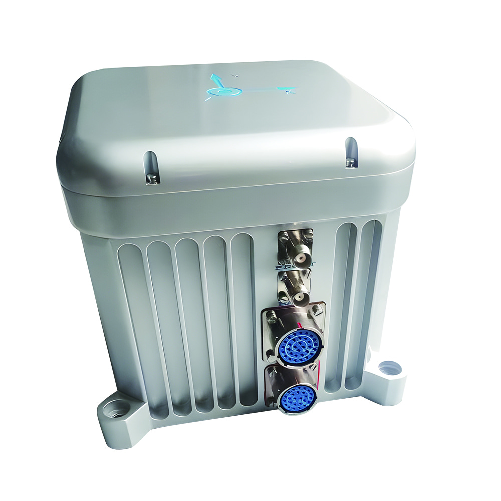
Product: MEMS Gyroscope Borehole North Finding System
Key Features:
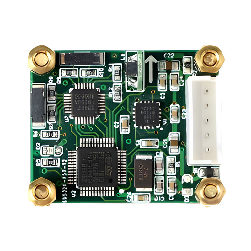
The new MEMS gyroscope is a kind of inertial gyro with simple structure, which has the advantages of low cost, small size and resistance to high shock vibration. The inertial north seeking gyroscope can complete the independent north seeking all weather without external restrictions, and can achieve fast, high efficiency, high precision and continuous work. Based on the advantages of MEMS gyro, MEMS gyro is very suitable for downhole north finding system. This paper describes the segmented fusion research of MEMS gyro borehole north finding system. The following will introduce the improved two-position north finding, the scheme of MEMS gyro borehole fusion north finding and the determination of north finding value.
The static two-position north seeking scheme generally selects 0° and 180° as the initial and end positions of north seeking. After repeated experiments, the gyro output angular velocity is collected, and the final north seeking Angle is obtained by combining the local latitude. The experiment adopted the two-position method every 10°, collected 360° of the turntable, and a total of 36 sets of data were collected. After averaging each set of data, the measured solution values were shown in Figure 1 below.

Figure 1 Fitting curve of gyroscope output from 0 to 360°
As can be seen from Figure 1, the output fitting curve is a cosine curve, but the experimental data and angles are still small, and the experimental results lack accuracy. Repeated experiments were conducted, and the Angle of acquisition was extended to 0~660°, and the two-position method was conducted every 10° from 0°, and the data results were shown in Figure 2. The trend of the image is cosine curve, and there are obvious differences in data distribution. At the crest and trough of the cosine curve, the distribution of data points is scattered and the degree of fit to the curve is low, while at the place with the highest slope of the curve, the fit of data points to the curve is more obvious.

Figure 2 Fitting curve of gyroscope output at two positions 0~660°
Combined with the relationship between azimuth and gyro output amplitude in Figure 3, it can be concluded that the data fit is better when the two-position north finding is adopted at 90° and 270°, indicating that it is easier and more accurate to detect the north Angle in the east-west direction. Therefore, 90°, 270°, instead of 0° and 180°, are used in this paper as the two-position north seeking gyro output acquisition positions.

Figure 3 Relation between azimuth and gyro output amplitude
When MEMS gyro is used in borehole north finding system, it is faced with complex environment, and there will be variable attitude Angle with drill bit drilling, so the solution of north Angle becomes much more complicated. In this section, based on the improvement of the two-position north finding scheme in the previous section, a method is proposed to obtain the attitude Angle by controlling rotation according to the output data information, and the included Angle with the north is obtained. The specific flow chart is shown in Figure 4.
The MEMS gyroscope is transmitted to the upper computer through RS232 data interface. As shown in Figure 4, after the initial north Angle is obtained by searching north at the two positions, the next step of drilling while drilling is carried out. After receiving the north seeking instruction, the drilling work stops. The attitude Angle output by MEMS gyro is collected and transmitted to the upper computer. The rotation of the borehole north seeking system is controlled by the attitude Angle information, and the roll Angle and pitch Angle are adjusted to 0. The heading Angle at this moment is the Angle between the sensitive axis and the magnetic north direction.
In this scheme, the Angle between MEMS gyroscope and true north direction can be obtained in real time by collecting attitude Angle information.

Figure 4 Fusion north finding flow chart
In the fusion north finding scheme, the improved two-position north finding was performed on the MEMS gyroscope. After the north finding was completed, the initial north position was obtained, the heading Angle θ was recorded, and the initial attitude state was (0,0,θ), as shown in Figure 5(a). When the bit is drilling, the attitude Angle of the gyroscope changes, and the roll Angle and pitch Angle are regulated by the rotary table, as shown in Figure 5(b).
As shown in Figure 5(b), when drilling the bit, the system receives the attitude Angle information of the attitude instrument, and needs to judge the sizes of roll Angle γ ‘and pitch Angle β’, and rotate them through the rotation control system to make them turn to 0. At this time, the output heading Angle data is the Angle between the sensitive axis and the magnetic north direction. The Angle between the sensitive axis and the true north direction should be obtained according to the relationship between the magnetic north and the true north direction, and the true north Angle should be obtained by combining the local magnetic declination Angle. The solution is as follows:
θ’=Φ-∆φ
In the above formula, θ ‘drill bit and the true north direction Angle, ∆φ is the local magnetic declination Angle, Φ is the drill bit and magnetic north Angle.

Figure 5 Change of initial and drilling attitude Angle
In this chapter, the north finding scheme of MEMS gyroscope underground north finding system is studied. Based on the two-position north finding scheme, an improved two-position north finding scheme with 90° and 270° as starting positions is proposed. With the continuous progress of MEMS gyroscope, MEMS north-seeking gyroscope can achieve independent north finding, such as MG2-101, its dynamic measurement range is 100°/s, can work in the environment of -40 ° C ~+85 ° C, its bias instability is 0.1°/hr, and the angular velocity random walk is 0.005°/√hr.
I hope you can understand the north finding scheme of MEMS gyroscope through this article, and look forward to discussing professional issues with you.

Xml Privacy Policy Blog Sitemap
copyright @ Micro-Magic Inc All Rights Reserved.
 Network Supported


 English