Key Points
Product: High-Performance Gyroscopes
Features:
Applications:
Advantages:
Limitations:
Summary: When choosing a gyroscope, it is necessary to consider minimizing the maximum error source. In most applications, vibration sensitivity is the largest source of error. Other parameters can be easily improved by calibration or taking the average of multiple sensors. Zero bias stability is one of the components with a smaller error budget.
When browsing high-performance gyroscope data manuals, the first element that most system designers focus on is the zero bias stability specification. After all, it describes the lower limit of the resolution of the gyroscope and is naturally the best indicator reflecting the performance of the gyroscope! However, actual gyroscopes may experience errors due to various reasons, making it impossible for users to obtain the high zero bias stability claimed in the data manual. Indeed, such high performance may only be achieved in the laboratory. The traditional method is to use compensation to minimize the impact of these error sources to the greatest extent possible. This article will discuss various such technologies and their limitations. Finally, we will discuss another alternative paradigm - selecting gyroscopes based on their mechanical performance and how to improve their bias stability if necessary.
All mid to low price MEMS gyroscopes have a certain time zero bias and scaling factor error, and also undergo certain changes with temperature. Therefore, temperature compensation for gyroscopes is a common practice. Generally speaking, the purpose of integrating temperature sensors into gyroscopes is for this purpose. The absolute accuracy of the temperature sensor is not important, what is important is repeatability and the close coupling between the temperature sensor and the actual temperature of the gyroscope. The temperature sensor of modern gyroscopes can almost effortlessly meet these requirements.
Many techniques can be used for temperature compensation, such as polynomial curve fitting, piecewise linear approximation, etc. As long as a sufficient number of temperature points are recorded and sufficient measures are taken during the calibration process, the specific technique used is irrelevant. For example, insufficient storage time at each temperature is a common source of error. However, no matter what technology is used or how careful, temperature hysteresis - the difference in output between cooling and heating to a specific temperature - will be the limiting factor.
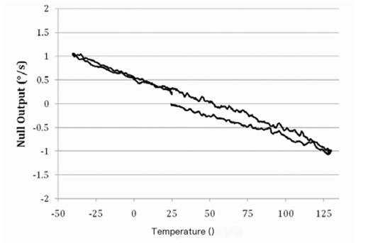
The temperature hysteresis loop of gyroscope ADXRS453 is shown in Figure 1. The temperature changes from+25 ° C to+130 ° C, then to -45 ° C, and finally back to+25 ° C, while recording the zero bias measurement results of the uncompensated gyroscope. There is a slight difference in the+25 ° C zero bias output between the heating cycle and the cooling cycle (approximately 0.2 °/s in this example), which is known as temperature hysteresis. This error cannot be eliminated through compensation, as it will occur regardless of whether the gyroscope is powered on or not. In addition, the magnitude of hysteresis is proportional to the amount of temperature "excitation" applied. That is to say, the wider the temperature range applied to the device, the greater the hysteresis.

Figure 1. Zero bias output of uncompensated ADXRS453 during temperature cycling (-45 ° C to+130 ° C)
If the application allows resetting the zero bias at startup (i.e. starting without rotation), or zeroing the zero bias on site, this error can be ignored. Otherwise, this may be a limiting factor for zero bias stability performance, as we cannot control transportation or storage conditions.
In an ideal situation, a gyroscope only measures the rotation rate and has nothing else to do with it. However, in practical applications, due to asymmetric mechanical design and/or insufficient precision in microfabrication, all gyroscopes have a certain degree of acceleration sensitivity. In fact, acceleration sensitivity has various external manifestations, and its severity varies depending on the design. The most significant sensitivity is usually the sensitivity to linear acceleration (or g-sensitivity) and the sensitivity to vibration correction (or g2 sensitivity). Due to the fact that most gyroscopes are used in devices that move and/or rotate in a 1g gravity field around the Earth, sensitivity to acceleration is often the largest source of error.
Low cost gyroscopes generally adopt extremely simple and compact mechanical system designs, and their anti vibration performance has not been optimized (it optimizes cost), so vibration may cause serious impacts. It is not surprising that the g sensitivity is above 1000 °/h/g (or 0.3 °/s/g), which is more than 10 times higher than that of high-performance gyroscopes! For this type of gyroscope, the stability of zero bias is of little significance. A slight rotation of the gyroscope in the Earth's gravity field can cause significant errors due to its sensitivity to g and g2. Generally speaking, this type of gyroscope does not specify vibration sensitivity - it defaults to very high.
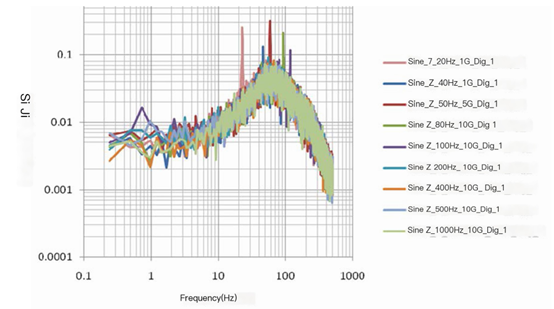
Some designers attempt to use external accelerometers to compensate for g-sensitivity (usually in IMU applications where the required accelerometer already exists), which can indeed improve performance in certain situations. However, due to various reasons, g sensitivity compensation cannot achieve complete success. The g-sensitivity of most gyroscopes varies with the frequency of vibration. Figure 2 shows the response of Silicon Sensing CRG20-01 gyroscope to vibration. Note that although the sensitivity of the gyroscope is within the rated specification range (slightly exceeding at some specific frequencies, which may not be important), the rate of change from DC to 100 Hz is 12:1, so calibration cannot be simply performed by measuring the sensitivity at DC. Indeed, the compensation plan will be very complex, requiring sensitivity to be changed according to frequency.

Figure 2. g-sensitivity response of Silicon Sensing CRG20-01 to different sine tones
Another difficulty is to match the phase response of the compensating accelerometer and gyroscope. If the phase response of the gyroscope and compensating accelerometer is not well matched, high-frequency vibration errors may actually be amplified! From this, another conclusion can be drawn: for most gyroscopes, g-sensitivity compensation is only effective at low frequencies. Vibration calibration is often not regulated, possibly due to embarrassing differences or significant differences between different components. It is also possible that it is simply because gyroscope manufacturers are unwilling to test or regulate (to be fair, testing may be difficult). Anyway, vibration correction must be taken into consideration as it cannot be compensated by an accelerometer. Unlike the response of an accelerometer, the output error of a gyroscope will be corrected.
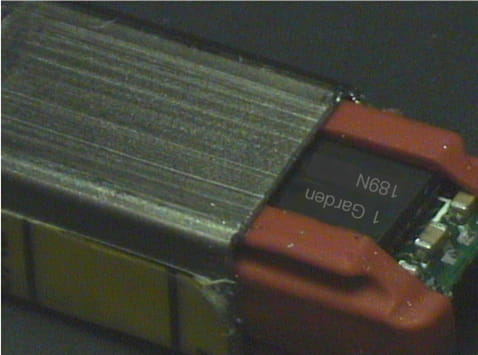
The most common strategy to improve the sensitivity of g2 is to add a mechanical anti vibration component, as shown in Figure 3. The picture shows a Panasonic car gyroscope partially removed from the metal cap shell package. The gyroscope component is isolated from the metal cap by a rubber anti vibration component. Anti vibration components are very difficult to design because their response is not flat over a wide frequency range (especially poor at low frequencies), and their damping characteristics vary with temperature and usage time. Like sensitivity, the vibration correction response of a gyroscope may vary with frequency. Even if anti vibration components can be successfully designed to attenuate narrowband vibrations in a known frequency spectrum, such anti vibration components are not suitable for general applications where wideband vibrations may exist.

Figure 3. Typical anti vibration components
In many applications, routine short-term abuse events may occur, which, although not causing damage to the gyroscope, can result in significant errors. Here are a few examples.
Some gyroscopes can withstand rate overload without exhibiting abnormal performance. Figure 4 shows the response of the Silicon Sensing CRG20 gyroscope to rate inputs that exceed the rated range by approximately 70%. The curve on the left shows the response of CRS20 when the rotation rate changes from 0 °/s to 500 °/s and remains constant. The curve on the right shows the response of the device when the input rate decreases from 500 °/s to 0 °/s. When the input rate exceeds the rated measurement range, the output oscillates randomly between tracks.

Figure 4. Response of Silicon Sensing CRG-20 to 500 °/s rate input
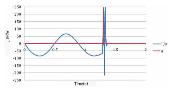
Some gyroscopes exhibit a tendency to 'lock' even when subjected to impacts of only a few hundred grams. For example, Figure 5 shows the response of VTI SCR1100-D04 to a 250 g 0.5 ms impact (the method of generating the impact is to drop a 5 mm steel ball from a height of 40 cm onto the PCB next to the gyroscope). The gyroscope was not damaged due to impact, but it no longer responds to rate input and needs to be turned off and powered on again to restart. This is not a rare phenomenon, as various gyroscopes exhibit similar behavior. It is wise to check whether the proposed gyroscope can withstand the impact in the application.

Figure 5. Response of VTI SCR1100-D04 to 250 g, 0.5 ms impact
Obviously, such errors will be astonishingly large. Therefore, it is necessary to carefully identify potential abuse situations in a given application and verify whether the gyroscope can withstand them.
In error budgeting, zero bias stability is one of the smallest components, so when choosing a gyroscope, a more reasonable approach is to consider minimizing the maximum error source. In most applications, vibration sensitivity is the largest source of error. However, sometimes users may still desire lower noise or better zero bias stability than the selected gyroscope. Fortunately, we have a way to solve this problem, which is to take the average.
Unlike design related environmental or vibration errors, the zero bias stability error of most gyroscopes has noise characteristics. That is to say, the zero bias stability of different devices is not correlated. Therefore, we can improve the zero bias stability performance by taking the average of multiple devices. If n devices are averaged, the expected improvement is √ n. Broadband noise can also be improved by a similar averaging method.
For a long time, zero bias stability has been regarded as the absolute standard for gyroscope specifications, but in practical applications, vibration sensitivity is often a more serious factor limiting performance. Choosing a gyroscope based on its anti-vibration capability is reasonable, as other parameters can be easily improved through calibration or averaging multiple sensors.
To calculate the error caused by vibration in a given application, it is necessary to understand the expected amplitude of acceleration and the frequency at which this acceleration may occur.
l Running typically produces a peak of 2 grams, accounting for approximately 4% of the time.
l The vibration of the helicopter is quite stable. Most helicopter specifications are 0.4 g wideband vibration and 100% duty cycle.
l Ships (especially small boats) on turbulent waters can tilt up to ± 30 ° (producing ± 0.5 g of vibration). The duty cycle can be assumed to be 20%.
l For construction equipment such as leveling machines and front-end loaders, as long as their blades or buckets hit stones, they will produce a high g (50 g) and brief impact. The typical duty cycle value is 1%.
When calculating the error caused by vibration, it is necessary to consider the sensitivity of g and g2. Taking helicopter application as an example, the calculation is as follows:
Error=[g sensitivity error]+[g2 sensitivity error]
=[0.4 g x g sensitivity x 3600 s/h x 100%]+
[(0.4 g) 2 × g2 sensitivity × 3600 s/h × 100%]
If the sensitivity of g is compensated by an accelerometer, only the sensitivity of g decreases, and the decrease is the compensation coefficient.


Xml Privacy Policy Blog Sitemap
copyright @ Micro-Magic Inc All Rights Reserved.
 Network Supported
