Explore high-precision calibration for FOG IMU (Fiber Optic Gyro Inertial Measurement Unit) across full temperature ranges. Learn key error modeling techniques, 3D bidirectional rate/one-position calibration, and Piecewise Linear Interpolation (PLI) compensation for enhanced navigation accuracy in drones, autonomous vehicles, and robotics.
How can FOG IMU (Inertial Measurement Unit based on Fiber Optic Gyroscope) maintain high precision in complex temperature environments? This article comprehensively analyzes its error modeling and compensation methods.
In modern aircraft, especially in small rotor unmanned aerial vehicle systems, FOG IMU is the core component of the navigation information and attitude measurement system. The fiber optic gyroscope (FOG) based on the Sagnac effect has advantages such as high precision, strong shock resistance, and fast response, but it has poor adaptability to temperature changes. This can easily lead to measurement errors during the flight process where the dynamic environment changes drastically, thereby affecting the performance of the overall navigation system.
The errors of FOG IMU can be mainly classified into two types:
(1) Angular velocity channel error: This includes installation error, proportional factor error, zero bias error, etc.

(2) Acceleration channel error: Mainly caused by installation error, temperature drift and dynamic disturbance.

These errors accumulate in the actual environment, seriously affecting the stability and accuracy of the flight control system.
Although traditional static multi-orientation calibration and angular velocity method can partially address the issue of errors, they have obvious shortcomings in the following aspects:
(1) Unable to balance accuracy and computational efficiency
(2) Inapplicable to full temperature range compensation
(3) Dynamic disturbances affect the stability of calibration
This requires a more intelligent and efficient error modeling and temperature compensation mechanism.
(1) Precise Calibration at Multiple Temperature Points
By setting multiple temperature points ranging from -10°C to 40°C and conducting three-axis rotation calibration at each point, temperature-related error parameters can be collected.
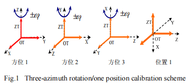
(2) Three-Dimensional Positive and Negative Speed Method: Precisely Simulating Real Flight Conditions
Using a single-axis rate turntable and a high-precision hexahedral tool, positive and negative speed calibration in the X/Y/Z axis directions can be achieved, enhancing the system's adaptability to dynamic environments.
(3) One-Axis Attitude Stabilization: Quickly Capturing System Zero Offset
While maintaining a static state, initial offsets under different temperatures are recorded to provide precise data support for subsequent error modeling.

To meet the error compensation requirements of FOG IMU across the entire temperature range, this paper proposes the Piecewise Linear Interpolation algorithm (PLI), which has the following characteristics:
(1) Low computational load: Suitable for embedded navigation systems with limited resources
(2) Strong real-time compensation capability: Error is dynamically adjusted with temperature changes
(3) Easy to deploy and upgrade
Compared with the high-order least squares method, the PLI scheme ensures the compensation accuracy while significantly reducing the system's computational burden, making it suitable for real-time computing scenarios during flight.
Through on-board field experiments, this method significantly enhanced the measurement accuracy and environmental adaptability of the system under various temperatures and dynamic disturbances, providing a solid navigation foundation for subsequent high-performance small rotorcraft flight platforms.
With the development of unmanned aerial vehicles and intelligent flight systems, the requirements for the accuracy of navigation systems have become increasingly stringent. By introducing the three-position positive and negative speed calibration and segmented linear interpolation compensation methods, the adaptability and accuracy of FOG IMU in the full temperature range and strong dynamic environment can be significantly improved. In the future, this technology is expected to play a greater role in autonomous driving, robot navigation, and high-precision map collection and other fields. Micro-Magic’s U-F3X80, U-F3X90, U-F3X100,and U-F300 , we can use full-temperature three-way positive and negative rate/one position calibration and PLI compensation method. According to the error characteristics of fiber optic gyro and quartz flexible accelerometer, the FOG inertial measurement unit error model is established, and the three-bit positive and negative rate/one-position calibration scheme is designed at each constant temperature point. The PLI algorithm is used to compensate the zero bias and scale factor temperature errors of the system in real time, reducing the calibration workload and the calculation amount of the compensation algorithm, and improving the system dynamics, temperature environment adaptability and measurement accuracy.

Xml Privacy Policy Blog Sitemap
copyright @ Micro-Magic Inc All Rights Reserved.
 Network Supported
