Home

Blog

Applications

  • Do you know why IMU is an irreplaceable part of drones?
    Do you know why IMU is an irreplaceable part of drones? Dec 03, 2024
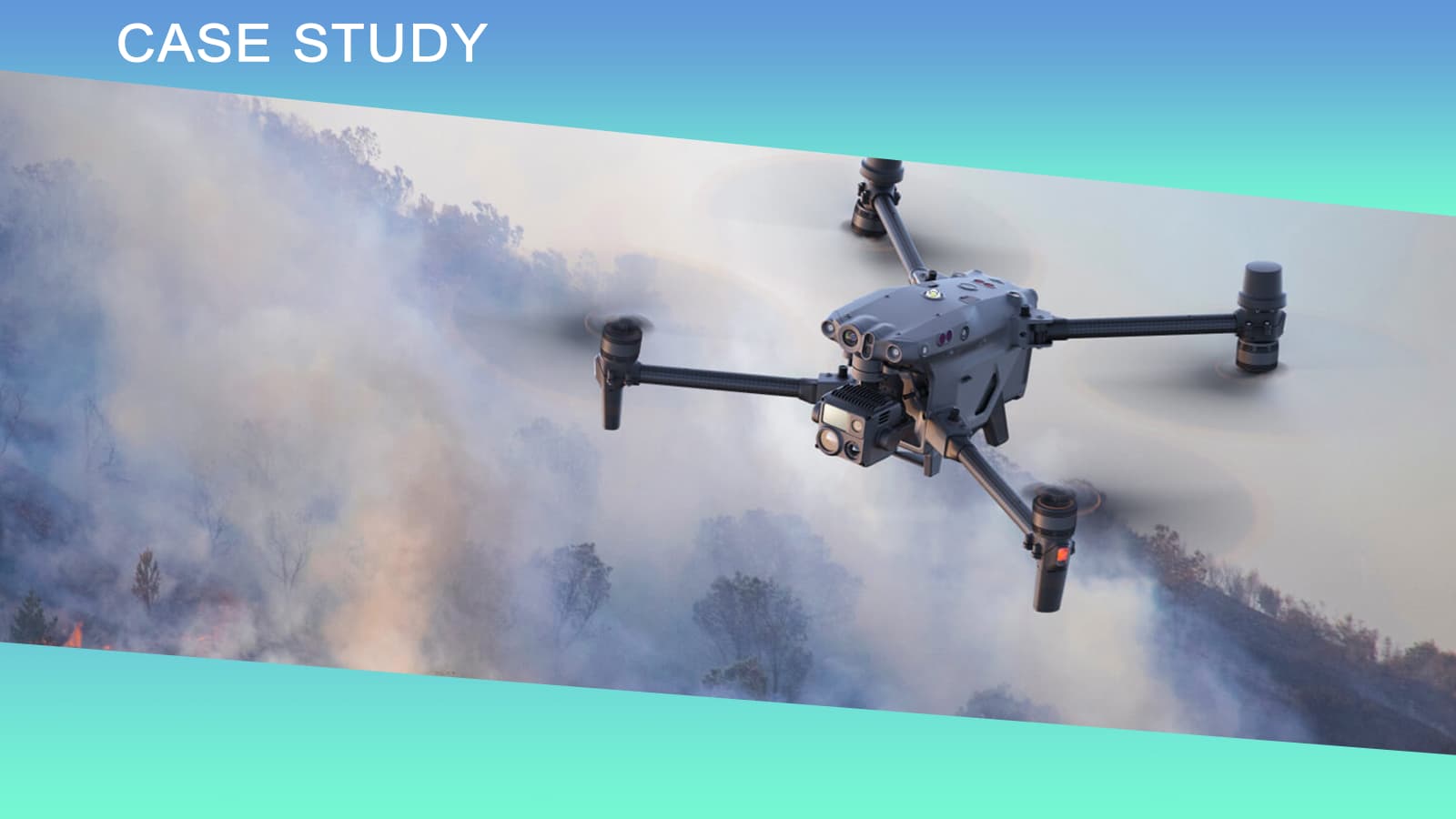
    Key Points    **Product**: Micro-Magic Inc’s MEMS IMU U5000, a tactical-grade, high precision, 9-axis IMU for drones.**Features**:  44.8×38.6×21.5mm size, 60g weight.  9-axis with a three-axis magnetometer.  Gyroscope: ±400º/s dynamic range, 0.5º/h bias instability, 0.08º/√h angular random walk.  Accelerometer: ±30g dynamic range, 0.01mg bias stability.  Power: 1.5W, energy-efficient for drones.**Advantages**: Suitable for drones, lightweight, cost-effective, mass-producible.**Magnetometer**: Helps with heading/yaw correction.   As one of the core components of drones, IMU plays an irreplaceable role. Its high precision, fast response and freedom from external interference enable drones to maintain stable and precise flight and accurate navigation and positioning in complex environments, and can also perform fault diagnosis for drones. Micro-Magic Inc’s MEMS IMU can achieve high performance while being small in size and light in weight, making it very suitable for drones.We have a tactical-grade IMU U5000 which is low-cost and has an advantage in price. It is a 9-axis IMU with an added three-axis magnetometer. It is only 44.8×38.6×21.5mm in size and weighs 60g. Compared with other IMUs, it is more suitable for drones. The built-in accelerometer of the IMU cannot be used to detect absolute heading (yaw). The magnetometer in this IMU measures the magnetic field strength in three dimensions, which can help determine the heading of the object as well as roll and pitch, and correct the integrated error of the yaw gyroscope in the sensor fusion algorithm.The dynamic measurement range of the built-in gyroscope is ±400º/s, the bias instability is 0.5 º/h, and the angular random walk is 0.08º/√h. The dynamic measurement range of the accelerometer is ±30g, the bias stability is 0.01mg (Allen variance).Considering the flight time requirements of drones, this IMU has a power of only 2W, which can extend the flight time of drones.This IMU has a short production cycle and can be mass-produced, which is particularly suitable for users with large demands and limited budgets.If you are interested in this and want to know more, please follow me and send me a message, I will reply immediately. I will update the relevant content later. U5000 Industrial Grade Temperature Compsensated Full Calibrated Strapdown 6Dof With Kalman Filter Algorithm U7000 Rs232/485 Gyroscope Imu For Radar/infrared antenna stabilization platform UF100A Middle Precision And Small Size IMU Fiber Optic Inertial Group    
  • Deep in the Mine, where is the Direction? FOG north finder, Trustworthy!
    Deep in the Mine, where is the Direction? FOG north finder, Trustworthy! Dec 20, 2024
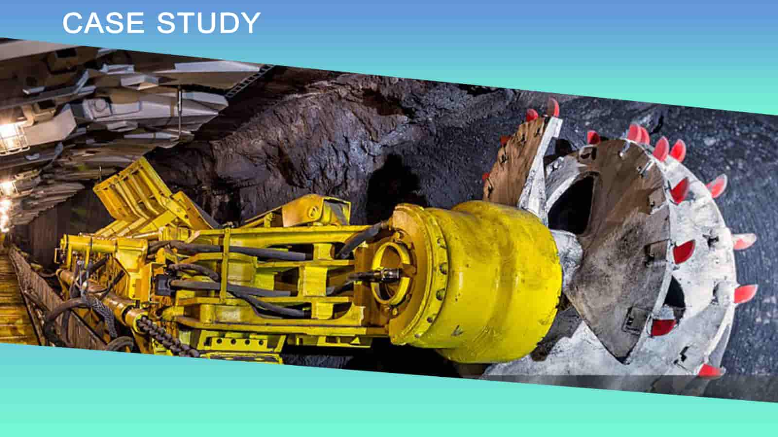
    Key Points **Product**: Micro-Magic Inc’s FOG North Finder NF 2000, a high-precision, solid-state north finder for mining and drilling. **Features**:– Core component: Closed-loop fiber optic gyroscope (FOG).– Three-axis design, 0.5°secψ (1σ) accuracy.– North-seeking time: 5 min.– Solid-state, no moving parts, long operational life.– Low power consumption, high efficiency. **Advantages**:– Independent of terrain and environmental conditions.– Reliable in underground or underwater mining.– Strong anti-interference, stable signal.– Portable options available for size-constrained applications. **Applications**: Ideal for coal, oil, and gas industries; enhances efficiency and cost reduction in mining operations. In the field of oil and coal mining, it is very important to obtain accurate north information. In terms of the selected methods, north-finding technology mainly includes inertial method, astronomical observation method, geodetic method, satellite positioning method and other methods. However, in complex terrain conditions such as underground tunnels or underwater, except for the inertial method, other methods will be restricted to varying degrees, and either have low accuracy or cannot be implemented at all.The inertial north-seeking technology of the north finder is not affected by natural conditions or the environment, can independently complete the north-seeking task, and has the characteristics of long continuous working time and high accuracy, so it is the most commonly used.Micro-Magic Inc has a FOG north finder NF 2000, which uses a closed-loop fiber optic gyroscope as its core component and can provide the carrier with a true north azimuth. Let’s see what’s special about it! FOG north finder, solid-state device, no moving parts, rock-solid!Low power consumption, worry-free long-term operation, lower cost, higher efficiency!Three-axis design, stable signal, 0.5°secψ(1σ) high accuracy, trustworthy!Strong anti-interference, wide measurement range, north-seeking time only 5 min!An ideal partner for the mining industry, improving efficiency and reducing costs!Widely used, a new choice of logging tools, efficient and accurate!Unlock new possibilities for accurate measurement for you with limited budget!Depending on the application environment, portable north finders are also developed. They are small in size and low in energy consumption, meeting the needs of some users who have requirements for product size. In addition, some north finders can also cope with harsh monitoring environments. For more information and data sheets, pricing, and other information, please email me and I will respond immediately. NF2000 Inertial Navigation System High Precision Fog North Seeker   NF3000 Road Roller Vibration Sensor 3 Axes Vibration Meter Price Quick Response Accelerometer Factory Price
  • Why Should We Use MEMS GNSS/INS?
    Why Should We Use MEMS GNSS/INS? Dec 20, 2024
    Key Points Product: Micro-Magic Inc’s MEMS GNSS/INS, including the I3500 model for mapping applications. Features: Size: Compact and lightweight for easy integration Accuracy: 2.5°/hr bias instability, 0.028°/√hr angular random walk MEMS accelerometer: ±6g range, zero bias instability <30μg GNSS integration for absolute positioning Advantages: Cost-effective, low power consumption, flexible placement, ideal for various applications like UAVs and aircraft, enhancing navigation precision through the fusion of INS and GNSS data. Compared to other INS solutions, a MEMS GNSS/INS has a lower size, weight, power consumption and cost. MEMS-based INS are suitable for most applications, including but not limited to: Marine Surveying, Land Surveying, UGVs, Helicopters, Antenna Targeting, Surveying, Robotics, UAVs. This article highlights five key benefits of using MEMS GNSS/INS. What is MEMS GNSS/INS? MINS/GNSS integrated navigation, refers to the fusion of information from both MINS (MEMS INS) and GNSS (Global Navigation Satellite System). This integration combines the strengths of both systems to complement each other and achieve accurate PVA (Position, Velocity, Attitude) results.The advantages and disadvantages of INS and GNSS are complementary. Therefore, combining the two technologies leverages their strengths to provide continuous, high-bandwidth, long-term, and short-term precise, comprehensive navigation parameters. In INS/GNSS or GNSS/INS integrated navigation systems, GNSS measurements suppress the drift of inertial navigation, while INS smooths the GNSS navigation results and compensates for signal interruptions. Five Reasons for Use MEMS GNSS/INS The manufacturing processes for MEMS devices are highly cost-effective due to mass production techniques used in the semiconductor industry. This results in lower production costs, making MEMS INS more affordable for a wide range of aviation applications. A MEMS GNSS/INS is not as costly as a FOG-based (fibre optic gyroscope) INS Lightweight and small By nature, MEMS are built on a miniature scale and measure in micrometres. This makes a MEMS-based INS an ideal fit for vehicles or machines that need a small payload.Take aviation for example, the compact size of MEMS GNSS/INS devices makes them ideal for use in aircraft where space is at a premium. This allows for easier integration into existing systems and more flexibility in aircraft design, potentially freeing up space for additional equipment or cargo. The lightweight nature of MEMS INS contributes to overall weight reduction in aircraft, which is crucial for enhancing fuel efficiency and performance. Lighter navigation systems allow for better payload capacity and improved aircraft range. Flexible placement The more compact nature of MEMS technology also allows the INS to be mounted in variable positions. The compact and efficient nature of MEMS INS makes them suitable for integration with advanced electronics and automation systems. This adaptability supports the development of more sophisticated management systems and enhances the overall functionality of modern aircraft. Low power consumption MEMS technology has advanced to the point where it can reduce power used, utilising power cycling and low power modes. MEMS GNSS/INS devices are designed to consume less power compared to traditional INS solutions. This reduced power consumption is beneficial for the electrical system, leading to lower operational costs and increased energy efficiency. For battery-powered applications, such as unmanned aerial vehicles (UAVs) or smaller aircraft, the lower power consumption of MEMS INS extends mission durations and operational capabilities, enabling longer flights and reducing the need for frequent recharges. GNSS integration With any kind of inertial navigation system, a MEMS GNSS/INS isn’t able to determine absolute position. By itself, the MEMS INS is able to determine the relative position of the vehicle from a known starting point, accounting for distance travelled and orientation. When a MEMS INS is combined with GNSS (global navigation satellite system) it takes advantage of the satellite technology to accurately determine the absolute position on Earth. With these two navigational technologies working in tandem, the strengths of both enable a high level of accuracy. An Excellent Solution Micro-Magic Inc is at the forefront of inertial navigation technology and has recently introduced three GNSS-aided MEMS INS products with varying levels of accuracy (mapping level, tactical level, and industrial level). Notably, the mapping level MEMS INS I3500 features a 2.5°/hr bias instability and a 0.028°/√hr angular random walk, along with a high-precision MEMS accelerometer with a large range (±6g, zero bias instability <30μg). More importantly, in an integrated navigation system, the INS leverages its high short-term accuracy to provide GNSS with continuous and comprehensive navigation information. Conversely, GNSS helps estimate INS error parameters, such as bias, resulting in more precise observations and reduced INS drift. GNSS offers stable long-term accuracy, provides initial values for position and speed, and corrects accumulated errors in the MEMS INS through filtering. The ER-GNSS/MINS-01 stands out as an excellent solution. I3500 High Accuracy 3-Axis Mems Gyro I3500 Inertial Navigation System I3700 High Accuracy Agricultural Gps Tracker Module Consumption Inertial Navigation System Mtk Rtk Gnss Rtk Antenna Rtk Algorithm I6700 Fiber Optic Three Axis Integrated Inertial Navigation System For Intelligent Navigation Fog Gyro Sensor
  • Do you Know What can Make Drones more Stable, Safe and Widely Used?
    Do you Know What can Make Drones more Stable, Safe and Widely Used? Dec 20, 2024
    Key Points Product: Micro-Magic Inc’s MEMS IMU U5000, a tactical-grade, low-cost, 9-axis IMU for drones. Features: Size: 44.8×38.6×21.5mm, Weight: ≤60g 9-axis with three-axis magnetometer and barometer Gyroscope: ±400º/s dynamic range, bias instability <0.5º/h, angular velocity random walk <0.08º/√h Accelerometer: ±30g dynamic range, bias repeatability 0.01mg Power: 2W, energy-efficient for extended flight Advantages: Ideal for drones, lightweight, cost-effective, and customizable for OEM, enhancing stability and performance with magnetometer aiding in heading correction. The key to achieving autonomous navigation, stable control and precise flight of drones is closely related to IMU, which is one of the core technologies of drone systems. At present, there are also research teams that have developed IMU-centric data-driven diagnostic methods to perform fault diagnosis on drones without the need for additional sensors. Choosing the right IMU can make flight more stable and safer.Micro-Magic Incs MEMS IMU U5000 and U7000 (can be customized for OEM) can be used in drones. Using MEMS technology, they are small in size, superior in performance, light in weight, low in power consumption, and cost-effective, and are very popular among users.Drones have strict requirements on the size and weight of IMUs. The U5000 has a size of (44.8×38.6×21.5mm(with shell)) and a weight of ≤60g (with shell). Flight control of drones is one of their most basic functions. MEMS IMU helps drones maintain a stable attitude by providing real-time acceleration and angular velocity data. The gyroscope measurement range of U5000 and U7000 is ±400deg/s, bias instability <0.5deg/hr, angular velocity random walk <0.08°/√h, accelerometer bias repeatability 0.01mg. At the same time, it has the characteristics of low power consumption, which prolongs the flight time of drones.It can also combine data from other sensors (such as GPS, magnetometer, etc.) to calculate the precise location and attitude information of the drone for navigation and positioning. When the drone is taking aerial photos, it can maintain extremely high stability to ensure the clarity and stability of the images and videos taken. At the same time, it can also be used as part of the drone’s fault safety system to detect abnormal movements or attitude changes and trigger automatic recovery procedures or emergency landing procedures to protect the safety of the drone and the surrounding environment.In the design and application of drones, high-performance IMUs are able to provide stable and accurate data under various environmental conditions, such as temperature changes, vibrations, and rapid movements, and perform precise tasks such as aerial photography, logistics transportation, and agricultural monitoring.MEMS IMU has many applications in the field of drones. They not only improve the performance and stability of drones, but also expand the scope of application of drones. If you are interested in this and want to know more, please follow me and send me a message. I will reply immediately. I will update the relevant content later. U5000 Industrial Grade Temperature Compsensated Full Calibrated Strapdown 6Dof With Kalman Filter Algorithm   U7000 Rs232/485 Gyroscope Imu For Radar/infrared antenna stabilization platform
  • Construction Of High-precision Miniaturized MEMS North Finder
    Construction Of High-precision Miniaturized MEMS North Finder Dec 23, 2024
    Key Points Product: High-precision Miniaturized MEMS North Finder Key Features: Components: Inertial Measurement Unit (IMU) with 3-axis MEMS gyroscope and accelerometer, plus power, control, and display circuits. Function: Provides accurate heading autonomously, unaffected by satellites or weather. Applications: Used in mining, oil logging, ships, and tunnels. Inertial Navigation: Measures position, velocity, and acceleration using gyroscopes and accelerometers. Conclusion: The MEMS North Finder is evolving in design, with models like the NF1000 adapting to cylindrical shapes for specialized industries like petroleum logging. As an instrument to measure the Angle between north and true north, North finder can provide accurate orientation and attitude information in the static base environment, and plays an important role in mining, oil logging, ship equipment, tunnel penetration and other fields. Nowadays, all walks of life have higher and higher requirements for the size and accuracy of the north seeker, so the north seeker is more high-precision and miniaturized. Originally, I will start from the basic point of view, focusing on the composition of the north seeking system, so that everyone can understand the north finder more clearly. The basic components of the north seeker The MEMS north finder can provide heading information to the moving body in a fully autonomous manner, working without relying on satellites, not affected by climate, and not requiring complex operations. It not only provides the data output interface for the computer, but also provides a good man-machine interface. The MEMS North finder is mainly composed of the inertial measurement module (IMU) and the line part, and the hardware block diagram is shown in Figure 1. Inertial measurement unit (IMU) is composed of gyroscope and rotary mechanism. The circuit part is mainly composed of four circuit boards, including: power board, control board, power amplifier board and base plate. Table 1 shows the components of the north seeking system. Figure 1 Hardware block diagram of the north seeker Table 1 Components of the North seeker There are two indicators on the panel of the MEMS north finder: north seeker indicator and power supply indicator; Two buttons: north button and power switch; A five-digit seven-segment digital display; A fuse; The device is externally connected with two connectors: a power socket and a communication interface socket.The North finder is composed of inertial measurement units and algorithms, which is the same principle as the inertial navigation system, the difference is that different algorithms form different systems. Therefore, the north seeking system is also an inertial navigation system.Inertial navigation system can measure position information, instantaneous velocity and acceleration and angular velocity through inertial measurement components without interference from external environment, without radiation and in secret, and can continuously provide position, attitude Angle, linear velocity, angular velocity and other parameter information in aviation, aerospace, navigation and military fields.The basic principle of inertial navigation is shown in Figure 2. The coordinate system shown in the figure is oxy, where (x,y) is the instantaneous position. On the platform of an inertial navigation system, the speed Vx, Vy and the instantaneous position x and y are obtained through computer calculation, where the x axis and y axis control the measurement axes of two accelerometers respectively, and the accelerometer is used to measure the acceleration of the two axes. Figure 2 Basic principle of inertial navigation In the inertial navigation system, the Earth’s surface is considered spherical, then the vector position is represented by the longitude and latitude and, if the x and y axes point north and east respectively, the vector position is represented by the longitude and latitude: Where R is the radius of the earth; φ0 – initial latitude of the carrier; λ0 – initial longitude of the carrier;φ – geographical latitude position of the carrier; λ – the geographical longitude position of the carrier;vx – northbound speed; vy – eastbound speed.An inertial measurement unit, also called an inertial navigation unit, consists of an accelerometer and a gyroscope. The inertial navigation system consists of three parts, including the inertial measurement unit, the computer and the display. The acceleration of the aircraft moving in three directions, transverse, longitudinal and vertical, is measured by three accelerometers, and the rotation of the aircraft in three directions, longitudinal and vertical, is measured by the gyroscope with three degrees of freedom. The computer calculates the plane’s speed and position; All kinds of navigation information data are displayed by the display. Conclusion Most of the north finder is a cube shape, but with the increasing demand of various industries, the appearance of the north seeker also changes. For example, the NF1000 is a north seeker designed for petroleum logging, directional drilling and mining, and its shape has made a big breakthrough, evolving from a cube to a cylinder, which can be well adapted to the shape of the probe. Since it is a MEMS north seeker, it contains a three-axis MEMS gyroscope and a three-axis MEMS accelerometer.I hope that through this article you can understand the structure of high-precision miniaturized MEMS north finder, if you are interested in more knowledge of north seeker, please contact us.     NF1000 Inertial Navigation System High Performance Dynamic MEMS North Seeker    
  • Material problems affecting the long-term stability of MEMS gyroscope accuracy and countermeasures
    Material problems affecting the long-term stability of MEMS gyroscope accuracy and countermeasures Dec 23, 2024
    Key Points **Product:** MEMS Gyroscope for Inertial Instruments **Features:** – **Materials:** Metal alloys, functional materials, organic polymers, inorganic non-metals– **Stability Influencers:** Microscopic defects, grain size, texture, internal stress– **Environmental Impact:** Performance affected by overload, vibration, and temperature cycling– **Microstructure Regulation:** Use of SiC/Al composites to reduce dislocation density and improve strength **Advantages:** Enhances long-term accuracy and stability, tailored microstructure control ensures reliability under varying conditions, crucial for applications in aerospace and precision logging. In recent years, with the rapid development of petroleum logging, aerospace, mining, surveying and mapping and other fields, the precision and long-term stability of precision instruments such as MEMS gyroscope has become more and more urgent. Studies have shown that the dimensional instability of materials is one of the main reasons for the poor accuracy and stability of inertial instruments. Dimensional stability is different from thermal expansion or thermal cycling performance, it is the main performance index of precision mechanical parts materials, refers to the ability of parts to maintain their original size and shape in a specific environment. MEMS gyroscope based inertial instrument material There are four main types of inertial instrument component materials, one is metal (such as aluminum and aluminum alloy, stainless steel, copper and copper alloy, titanium alloy, beryllium, gold, etc.) and its composite materials; Second, functional materials (such as iron-nickel soft magnetic alloy, samarium-cobalt hard magnetic alloy, Al-nickel-cobalt hard magnetic alloy, etc.); Third, organic polymers (such as polytetrafluoroethylene, rubber, epoxy resin, etc.); The fourth is inorganic non-metal (such as quartz glass, processable ceramics, etc.), of which the largest amount is metal and its composite materials. In recent years, we have made breakthroughs in high-precision machining manufacturing, low/stress-free assembly technology, but we still find that after the delivery of the instrument, there is a slow drift in accuracy and cannot achieve long-term stability. In fact, after the structural design, parts processing and assembly process is determined, the long-term stability of the instrument accuracy depends on the intrinsic characteristics of the material. The intrinsic properties of the material (such as microscopic defects, second phase, grain size, texture, etc.) directly affect the dimensional stability of the material. In addition, the instrument material will also undergo irreversible dimensional changes under the interaction with the external environment (stress field, temperature field and time, etc.). Figure 1 shows the relationship between the accuracy of the inertial instrument and the service conditions, material microstructure and size change. Taking MEMS gyroscope as an example, its working conditions and storage environment have an impact on the dimensional stability of the material. Even if the MEMS gyroscope has a temperature control system, if the microstructure of the material itself is unstable, there is a metastable second phase, or there is macro/micro residual stress during assembly, the accuracy of the instrument will drift. Figure 1 The relationship among the accuracy of inertial instruments, service conditions,  microstructure and dimensional changes Influencing factors of material change The intrinsic properties of MEMS gyroscope materials mainly include microscopic defects, second phase, grain, texture and internal stress, etc. The external environmental factors mainly interact with the intrinsic properties to cause dimensional changes. 1. Density and morphology of microscopic defects Microscopic defects in metals and alloys include vacancies, dislocations, twins and grain boundaries, etc. Dislocation is the most typical form of microscopic defect, which refers to the defects formed by irregular arrangement of atoms in regularly arranged crystals, such as the absence or increase of half atomic plane of edge dislocation. Due to the dislocation introducing free volume into perfect crystals, the material size changes are caused, as shown in Figure 2. However, in the case of the same number of atoms, the existence of dislocation makes the free volume around the atoms appear, which is reflected in the increase of the alloy size. Figure 2 Schematic of the effect of the microscopic defects density in materials on the dimension of the material 2. Influence of grain and texture on stability The relationship between the strain ε of the metal or alloy under applied stress σ and the grain size d of the material, the density ρ of the movable dislocation, the stress σ0 required for the first dislocation to start, and the shear modulus G of the material is derived: It can be seen from the formula that grain refinement can reduce the strain generated, which is also the guiding direction of microstructure regulation in the stabilization process.In addition, in actual production, when using extruded bars and rolled plates to process precision instrument components, it is also necessary to pay attention to the anisotropy of the material, as shown in Figure 3. Taking 2024Al alloy for mechanical gyro frame as an example, the frame in figure 3(a) generally adopts extruded 2024 aluminum alloy bar. Due to large plastic deformation, the grains will show preferential orientation to form texture, as shown in figure 3(b) and (c), texture refers to the state in which the crystal orientation of the polycrystalline material deviates significantly from random distribution. Figure 3 Microstructure of 2024Al alloy rod for mechanical gyroscope frames Products in Article 3. The influence of environment on the dimensional stability of materials   In general, inertial instruments need to maintain long-term accuracy stability under conditions such as large overload, vibration and shock, and temperature cycling, which puts forward more demanding stabilization requirements for the microstructure and properties of materials. Taking instrument-grade SiC/2024Al composites as an example, long-term dimensional stability is achieved with stabilization process in the manufacturing of inertial instrument structures. The results show that the size change amplitude (~ 1.5×10⁻⁴) caused by the constant temperature holding process of SiC/ pure aluminum composite (only the internal stress plays an effect on the size change) is greater than that of the aluminum alloy constant temperature holding process (only the aging precipitation plays an effect on the size change) (~ -0.8×10⁻⁴). When the matrix becomes Al alloy, the effect of the internal stress of the composite on the dimensional change will be further amplified, as shown in Figure 4. In addition, under different service environments, the internal stress change trend of the same material is different, and even the opposite size change trend will be shown. For example,SiC/2024Al composites produce compressive stress release at a constant temperature of 190 ° C, and the size increases, while tensile stress release occurs at 500 cold and hot shocks at -196 ~ 190 ° C, and the size decreases. Therefore, when designing and using aluminum matrix composites, it is necessary to fully verify their service temperature load, initial stress state and the type of matrix material. At present, the process design idea based on stress stabilization is to carry out cold and thermal shock covering its service temperature range, release internal stress, form a large number of stable dislocation structures inside the composite material, and promote a large number of secondary precipitation. Figure 4 Dimensional changes in aluminium alloys and composites during constant temperature aging Measures to improve dimensional stability of components 1. Regulation and optimization of micro-defects Selecting new material system is an effective way to control micro-defects. For example, the use of instrument-grade SiC/Al composites,SiC ceramic particles to pin the dislocation in the aluminum matrix, reduce the density of movable dislocation, or change the type of defect in the metal. Taking SiC/Al composites as an example, the research shows that when the average distance between ceramic particles in the composites is reduced to 250 nm, the composite with layer fault can be prepared, and the elastic limit of the composite with layer fault is 50% higher than that of the composite without layer fault, as shown in Figure 5. Figure 5 Two kinds of composite material morphology It should be pointed out that when developing the process route of organizational control, it is also necessary to select the appropriate material system and cold and thermal shock process parameters in combination with the stress conditions and working temperature range of the inertial instrument service environment. In the past, the selection of material system and process parameters relied on experience and a large number of performance data, which resulted in insufficient theoretical basis for process design due to the lack of micro-structure support. In recent years, with the continuous development of analytical testing technology, quantitative or semi-quantitative evaluation of microscopic defect density and morphology can be achieved by means of X-ray diffractometer, scanning electron microscope and transmission electron microscope, which provides technical support for material system optimization and process screening.   2. Regulation of grain and texture   The effect of texture on dimensional stability is the anisotropy that causes the dimensional change. As mentioned earlier, the MEMS gyroscope frame has extremely strict vertical requirements in the axial and radial direction, and the processing error is required to be controlled in the order of microns to avoid causing the centroid deviation of the MEMS gyroscope. For this reason, the 2024Al extruded bar was subjected to deformation heat treatment. Figure 6 shows the metallographic photos of 40% axial compression deformation of the extruded 2024 aluminum alloy and the microstructure photos before and after thermal deformation. Before the deformation heat treatment, it is difficult to calculate the size of the axial grain, but after the deformation heat treatment, the equiaxial degree of the grain at the edge of the bar is 0.98, and the equiaxial degree of the grain is significantly increased. In addition, it can be seen from the figure that the small deformation resistance difference between the axial and radial of the original sample is 111.63MPa, showing strong anisotropy. After deformation heat treatment, the axial and radial small deformation resistance values were 163 MPa and 149 MPa, respectively. Compared with the original sample, the ratio of axial and radial small deformation resistance changed from 2.3 before deformation heat treatment to 1.1, indicating that the anisotropy of the material was better eliminated after deformation heat treatment. Figure 6 Schematic diagram of isotropic treatment, microstructure changes, and performance testing of aluminum alloy rod Therefore, when aluminum alloy bars or plates must be used to process inertial instrument components, it is recommended to increase the deformation heat treatment link, eliminate the texture, obtain isotropic organization, and avoid the anisotropy of deformation. The statistical information of texture can be obtained by EBSD in SEM, TKD in TEM or three-dimensional XRD, and the texture changes can be quantitatively analyzed. Conclusion Based on the urgent need of long-term accuracy stability of inertial instruments, this paper systematically reviews the influence of dimensional stability from the perspective of material science, and puts forward how to improve the long-term accuracy stability of inertial instruments from the intrinsic characteristics of materials. The NF-1000, in an LCC ceramic package, is an upgraded north-finding MEMS gyroscope based on the MG-502, and its range has been increased from 50-100°/s to 500°/s, achieving a milestone. Materials are critical to the long-term stability of , and it is the basis for their best performance.   I hope that through this article you can understand the knowledge of MEMS gyro, want to know more information can read related products and articles.   MG502 Mg-502 High Precision Mems Single Axis Gyroscopes    
  • Navigation grade MEMS IMU VS Tactical grade MEMS IMU
    Navigation grade MEMS IMU VS Tactical grade MEMS IMU Dec 23, 2024
    Key Points Product: Micro-Magic Inc’s MEMS IMU UF300A (Navigation-grade) vs UF100A (Tactical-grade). Navigation-grade UF300A Features: Size: Compact for various applications Gyroscope: Bias repeatability <0.05°/hr, bandwidth 100Hz Accelerometer: High precision for navigation tasks Power: Efficient for long-duration use Tactical-grade UF100A Features: Size: Similar compact design Gyroscope: Bias repeatability <0.2°/hr, bandwidth 300Hz Accelerometer: Robust for tactical missions Power: Optimized for demanding environments Advantages: UF300A excels in precision for navigation; UF100A is tailored for high-precision applications like drone navigation and stabilization, offering flexibility and reliability in critical tasks. Introduce Navigation-grade IMU and Tactical-grade IMU are different levels of inertial measurement units (IMU). They have significant differences in accuracy, performance and application scenarios. Navigation-level and tactical-level IMU will be introduced below. Navigation grade MEMS IMU First of all, navigation-grade IMU is mainly used for general navigation and positioning tasks, and its performance requirements are relatively low. It usually has high accuracy and reliability and can meet the needs of most navigation applications. Through internal sensors such as accelerometers and gyroscopes, the navigation-grade IMU can accurately measure key information such as the acceleration, angular velocity, and direction of objects. After processing, this information can be used to achieve precise positioning and navigation functions, thereby improving driving safety and stability. Tactical Grade MEMS IMU Tactical-grade IMU have some unique core features. For example, they are able to operate gyroscopes with extremely low bias stability, meaning that bias errors become more stable over time. This stability is critical for high-precision applications such as drone navigation. And for higher-precision applications, such as drone navigation, antenna and weapon platform stabilization, tactical-grade IMU are required. Gyroscopes are known to operate with extremely low bias stability, meaning their bias errors remain relatively stable over time. This feature allows tactical-grade IMU to maintain excellent performance in long-term, high-precision applications. In addition, tactical-grade IMU are usually equipped with high-quality MEMS accelerometers and gyroscopes to provide more accurate data output.   It can be seen that navigation-grade IMU and tactical-grade IMU have different emphasis on accuracy, performance and application scenarios. When selecting an IMU, the most appropriate level needs to be determined based on specific application requirements. The following will briefly describe the differences between navigation-grade MEMS IMU and tactical-grade MEMS IMU, and introduce two IMU from the domestic inertial navigation company Micro-Magic Inc. Navigation grade MEMS IMU VS Tactical grade MEMS IMU There are significant differences in performance and application between navigation-grade IMU and tactical-grade IMU. First, navigation-grade IMU are usually used in some scenarios with relatively high accuracy requirements, and their performance and accuracy are higher than tactical-grade IMU. The performance and accuracy of tactical-grade IMUs are far inferior to those of navigation-grade IMU, so tactical-grade IMUs are the first choice for demanding applications such as drone navigation. These IMU operate gyroscopes with extremely low bias stability, which means that the bias error becomes more stable over time. This feature is essential for critical missions and high-precision applications such as drone navigation, antenna and weapon platform stabilization. Micro-Magic Inc is an inertial navigation company that independently develops MEMS IMU. The MEMS IMU it develops are mainly divided into navigation level and tactical level. The following are the company’s UF300A(navigation level) and UF100A (tactical level). Level) built-in MEMS gyroscope specification comparison:   UF100A UF300A Bias repeatability <0.2deg/hr <0.05deg/hr Range 300 300 Bias stability (10s 1σ) <0.2deg/hr <0.05deg/hr Bandwidth (-3dB) 300Hz 100Hz Threshold <0.1°/√h <0.005°/ √h It can be seen from the above table that the accuracy of the built-in gyroscope of the navigation-grade MEMS IMU is much higher than that of the tactical-grade one, especially the bias repeatability of the navigation-grade one is 0.05, and the tactical-grade one is 0.2. The accuracy is much higher. NF100A has a larger range than NF300A. Summarize Navigation-grade IMU and tactical-grade IMU are different in accuracy, stability and applicable scenarios. When selecting, the most appropriate IMU type needs to be determined based on specific application requirements. For more professional information, please consult our relevant personnel. UF100A Middle Precision And Small Size IMU Fiber Optic Inertial Group   UF300 High-precision Miniaturized Inertial Measurement Unit Fiber Optic Inertial Measurement Unit  
  • Solutions for Effective Tilt Sensing Using MEMS Accelerometers
    Solutions for Effective Tilt Sensing Using MEMS Accelerometers Dec 23, 2024
    Key Points Product: ACM 1200 High Accuracy MEMS Accelerometer Features: Bias Stability: 100 mg for reliable zero-g offset Resolution: 0.3 mg for precise measurements Temperature Range: Factory calibrated from -40°C to +80°C Applications: Designed for inclination monitoring in hydraulic structures, civil engineering, and infrastructure Advantages: High precision (0.1° tilt accuracy), effective in dynamic environments, addresses key criteria like low noise, repeatability, and cross-axis sensitivity, enhancing long-term reliability and performance in tilt sensing systems. In the field of MEMS systems, capacitive accelerometers have become a cornerstone technology for inclination or tilt sensing. These devices, essential for various industrial and consumer applications, face significant challenges, especially in dynamic environments where vibration and shock are prevalent. Achieving high precision, such as 0.1° tilt accuracy, requires addressing a range of technical specifications and error factors. This article delves into the key criteria and solutions for effective tilt sensing using MEMS accelerometers. 1.Key Criteria for Accurate Tilt Sensing Bias Stability: Bias stability refers to the accelerometer’s ability to maintain a consistent zero-g offset over time. High bias stability ensures that the sensor readings remain reliable and do not drift, which is crucial for maintaining accuracy in tilt measurements.   Offset Over Temperature: Temperature variations can cause shifts in the accelerometer’s zero-g offset. Minimizing these shifts, known as tempco offset, is essential to maintain accuracy across different operating conditions. Low Noise: Noise in sensor readings can significantly affect the accuracy of tilt measurements. Low-noise accelerometers are vital for achieving precise and stable tilt readings, particularly in static environments. Repeatability: Repeatability refers to the sensor’s ability to produce the same output under identical conditions over multiple trials. High repeatability ensures consistent performance, which is critical for reliable tilt sensing. Vibration Rectification: In dynamic environments, vibration can distort tilt data. Effective vibration rectification minimizes the impact of these disturbances, allowing for accurate tilt measurements even when the sensor is subjected to external vibrations. Cross-Axis Sensitivity: This parameter measures how much the sensor output is affected by accelerations perpendicular to the measurement axis. Low cross-axis sensitivity is essential to ensure that the accelerometer responds accurately to tilt along the intended axis only. 2.Challenges in Dynamic Environments Dynamic environments pose significant challenges for MEMS accelerometers in tilt sensing applications. Vibration and shock can introduce errors that corrupt tilt data, leading to significant measurement inaccuracies. For instance, achieving <1° tilt accuracy is extremely challenging in such conditions, while attaining >1° accuracy is more feasible. Understanding the sensor’s performance and the application’s environmental conditions is crucial to optimizing tilt measurement accuracy. 3.Error Sources and Mitigation Strategies Several error sources can affect the accuracy of MEMS accelerometers in tilt sensing:   Zero-g Bias Accuracy and Shift: Zero-g bias errors can arise from soldering, PCB enclosure alignment, and temperature changes. Postassembly calibration can reduce these errors. Sensitivity Accuracy and Tempco: Variations in sensitivity due to temperature changes must be minimized to ensure accurate readings. Nonlinearity: Nonlinear responses can distort measurements and need to be corrected through calibration. Hysteresis and Long-Term Stability: Hysteresis and stability over the sensor’s lifetime can impact accuracy. These issues are often addressed through high-quality manufacturing and design practices. Humidity and PCB Bending: Environmental factors such as humidity and mechanical stresses from PCB bending can introduce additional errors. In-situ servicing and environmental controls are necessary to mitigate these effects. For example, the ACM 1200 High Accuracy MEMS Accelerometer is tailored specifically for inclination applications. It boasts the bias stability of 100 mg and resolution of 0.3 mg The factory calibration characterizes the entire sensor signal chain for sensitivity and bias over a specified temperature range (typically −40°C to +80°C), ensuring high precision and reliability upon installation. It is suitable for long-term installation in hydraulic structures such as concrete dams, panel dams, and earth-rock dams, as well as in civil and industrial buildings, roads, bridges, tunnels, roadbeds, and civil engineering foundations. It facilitates the measurement of inclination changes and enables the automated collection of measurement data. 4. Conclusion MEMS capacitive accelerometers are pivotal in achieving accurate tilt sensing, but they must overcome various challenges, especially in dynamic environments. Key criteria such as bias stability, offset over temperature, low noise, repeatability, vibration rectification, and cross-axis sensitivity play critical roles in ensuring precise measurements. Addressing error sources through calibration and employing integrated solutions like iSensors can significantly enhance the performance and reliability of tilt sensing systems. As technology advances, these sensors will continue to evolve, offering even greater accuracy and robustness for a wide range of applications.   ACM1200 High Performance Industry Current Type Mems Accelerometer Sensor Factory    
  • Common Solutions for GNSS/INS Integrated Navigation Under Satellite Signal Loss
    Common Solutions for GNSS/INS Integrated Navigation Under Satellite Signal Loss Jan 06, 2025
    Key Points Product: GNSS/INS Integrated Navigation Solutions Key Features: Components: Integrated system includes GNSS receiver, Inertial Measurement Unit (IMU), and optional sensors like LiDAR or odometers. Function: Maintains accuracy and stability during GNSS signal loss using additional sensors or motion state constraints like ZUPT. Applications: Ideal for urban navigation, mining, oil logging, and other environments with potential signal obstructions. Inertial Navigation: Utilizes gyroscopes and accelerometers to measure position, velocity, and acceleration. Conclusion: The integrated system’s design is evolving, with solutions that enhance robustness in challenging environments while balancing cost and complexity. In a GNSS/INS integrated navigation system, GNSS measurements play a critical role in correcting the INS. Therefore, the proper functioning of the integrated system depends on the continuity and stability of the satellite signals. However, when the system operates under overpasses, tree canopies, or within urban buildings, the satellite signals can easily be obstructed or interfered with, potentially leading to a loss of lock in the GNSS receiver.This article discusses solutions for maintaining the accuracy and stability of GNSS/INS integrated navigation systems when satellite signals are lost. When the satellite signal is unavailable for an extended period, the lack of GNSS corrections causes the INS errors to accumulate rapidly, especially in systems with lower-precision inertial measurement units. This issue leads to a decline in the accuracy, stability, and continuity of the integrated system’s operation. Consequently, it is essential to address this problem to enhance the robustness of the integrated system in such complex environments. 1.Two Main Solutions to Address Signal Loss of GNSS/INS Currently, there are two main solutions to address the scenario of satellite signal loss. Solution 1: Integrate Additional Sensors On one hand, additional sensors can be integrated into the existing GNSS/INS system, such as odometers, LiDAR, astronomical sensors, and visual sensors. Thus, when satellite signal loss renders the GNSS unavailable, the newly added sensors can provide measurement information and form a new integrated system with the INS to suppress the accumulation of INS errors. The issues with this approach include increased system costs due to the additional sensors and potential design complexity if the new sensors require complex filtering models. Fig.1 System overview of the GNSS IMU ODO LiDAR SLAM integrated navigation system. Solution 2: ZUPT Technology On the other hand, a positioning model with motion state constraints can be established based on the motion characteristics of the vehicle. This method does not require adding new sensors to the existing integrated system, thus avoiding extra costs. When GNSS is unavailable, the new measurement information is provided by the motion state constraints to suppress the INS divergence. For example, when the vehicle is stationary, zero-velocity update (ZUPT) technology can be applied to suppress the accumulation of INS errors. ZUPT is a low-cost and commonly used method to mitigate INS divergence. When the vehicle is stationary, the vehicle’s speed should theoretically be zero. However, due to the accumulation of INS errors over time, the output speed is not zero, so the INS output speed can be used as a measurement of the speed error. Thus, based on the constraint that the vehicle’s speed is zero, a corresponding measurement equation can be established, providing measurement information for the integrated system and suppressing the accumulation of INS errors. Fig.2 The flowchart of the ZUPT-based GNSSIMU tightly coupled algorithm with CERAV. However, the application of ZUPT requires the vehicle to be stationary, making it a static zero-velocity update technology that cannot provide measurement information during normal vehicle maneuvers. In practical applications, this requires the vehicle to frequently stop from a moving state, reducing its maneuverability. Additionally, ZUPT requires accurate detection of the vehicle’s stationary moments. If detection fails, incorrect measurement information may be provided, potentially leading to the failure of this method and even causing the integrated system’s accuracy to decline or diverge. Conclusion The loss of satellite signals can cause rapid error accumulation in the INS, particularly in complex environments like urban areas. Two main solutions are presented: adding additional sensors, such as LiDAR or visual sensors, to provide alternative measurements, or using motion state constraints like Zero-Velocity Update (ZUPT) technology to correct INS errors. Each approach has its own advantages and challenges, with sensor integration increasing costs and complexity, while ZUPT requires the vehicle to be stationary and accurately detected to be effective. Micro-Magic Inc is at the forefront of inertial navigation technology and has recently introduced three GNSS-aided MEMS INS products with varying levels of accuracy ( industrial level,tactical level, and Navigation level). Notably, the Industrial level MEMS GNSS/INS I3500 features a 2.5°/hr bias instability and a 0.028°/√hr angular random walk, along with a high-precision MEMS accelerometer with a large range (±6g, zero bias instability <30μg). I3500 High Accuracy 3-Axis Mems Gyro I3500 Inertial Navigation System   I3700 High Accuracy Agricultural Gps Tracker Module Consumption Inertial Navigation System Mtk Rtk Gnss Rtk Antenna Rtk Algorithm    
  • A Closed-loop Test Method for Damping Coefficient of Q-Flex Accelerometer
    A Closed-loop Test Method for Damping Coefficient of Q-Flex Accelerometer Jan 10, 2025
    Key Points Product: Q-Flex Quartz Accelerometer Key Features: Components: High-purity quartz pendulum design with a closed-loop feedback system for precise acceleration measurements. Function: Provides accurate, stable acceleration data, with low noise and good long-term stability, especially effective in closed-loop operation. Applications: Ideal for aircraft navigation and attitude control, geological exploration, and industrial environments requiring precise inertial measurements. Measurement Method: Closed-loop frequency response measurement, ensuring reliable damping parameter estimation and accurate performance. Conclusion: The Q-Flex accelerometer offers high precision and stability, making it valuable for navigation, control, and industrial measurement applications. Q-Flex accelerometer is a kind of inertial measurement device, which utilizes the quartz pendulum to measure the acceleration of the object by the characteristic of deviating from the equilibrium position by the inertial force. Thanks to the low temperature coefficient of high-purity quartz material and stable structural characteristics, Q-Flex accelerometer has high measurement accuracy, low measurement noise, good long-term stability, and is widely used in attitude control, navigation and guidance of aircraft, as well as geological exploration and other industrial environments. 1.Detection method for Q-Flex Accelerometer When the system is open-loop, because the system can not produce feedback moment, the pendulum assembly is subjected to weak inertia moment or the active moment of the torque converter, the quartz pendulum easily touches the yoke iron and saturated phenomenon, which makes it very difficult to test the damping parameters under the open-loop, therefore, the damping parameters are considered to be measured under the closed-loop state of the system. The closed-loop frequency characteristics of the control system reflect the variation of the amplitude and phase of the output signal with the frequency of the input signal. The frequency response of the stabilized system is at the same frequency as the input signal, and its amplitude and phase are functions of the frequency, so the amplitude-phase characteristic curve of the frequency response can be applied to determine the mathematical model of the system. In order to obtain the actual damping parameters of the accelerometer, the closed-loop frequency response measurement method is used. In the closed-loop frequency response measurement method, the accelerometer is fixed on the horizontal vibration table in the “pendulum” state, so that the acceleration input direction of the vibration table is aligned with the sensitive axis of the accelerometer and the accelerometer is placed horizontally in the “pendulum” state, which can eliminate the asymmetry of the gravitational force on the input acceleration. The horizontal placement of the accelerometer in the “pendulum state” eliminates the effect of gravity on the asymmetry of the input acceleration. Fig.1 Close Loop amplitude Frequency characteristic curve of qfas By controlling the horizontal shaker, a sinusoidal acceleration signal of 6 g (g is the acceleration of gravity, 1 g ≈ 9.8 m/s2), with a gradually increasing frequency from 0 to 600 Hz, is applied to the Q-Flex accelerometer, which can reflect the amplitude attenuation and phase delay of the output of the accelerometer within the design range and bandwidth of the accelerometer. Accelerometer will produce the corresponding output under the action of the shaking table, the high sampling rate recorder connected to both sides of the sampling resistance, recording the output of the accelerometer, and plot the amplitude-frequency characteristic curve shown in Figure 1. In the passband of the accelerometer amplitude-frequency characteristic curve, the quartz flexural accelerometer maintains a good acceleration following ability, with the increase of the input acceleration frequency, the system resonance peak at 565Hz, the resonance peak is Mr=32dB, the cutoff frequency of the system is 582Hz, the amplitude of the system at the frequency began to produce more than 3dB of attenuation. Since the rotational inertia, stiffness and the rest of the parameters of the servo control loop of the Q-Flex accelerometer are known, the amplitude-frequency characteristics of the system are used to solve for the unknown parameter δ. The closed-loop transfer function of the system is given as Equation 1 The least-squares method estimates the parameters of the model based on the actual observed data, and a set of frequency amplitude data is obtained by generating an external acceleration input through a horizontal shaker, which is measured by a pen register, as shown in Table 1. Tab.1 Frequency Amplitudesamplingdataofqfas The amplitude-frequency response function of the quartz flexural accelerometer system with known parameters is the objective function, and the residual sum of squares with unknown parameters is established as Equation 2 Where, n is the number of selected feature points. Using the above equation, a suitable value of δ is selected so that D(δ) has the minimum value. The desired damping coefficient is obtained as δ=7.54×10⁻⁴N·m·s/rad using least squares fitting. The closed-loop simulation model of the system is established, and the damping coefficient is substituted into the quartz flexural accelerometer head model and the system is simulated, and the amplitude-frequency characteristic curve of the system is plotted as shown in Fig. 2, which is closer to the measured curve. Fig.2 Realityamplitude Frequency characteristic and parametrics imulation output Some studies have solved the damping distribution of the piezoelectric film on the surface of the pendulum by the finite time domain difference method, and the damping coefficient of the piezoelectric film of the pendulum is 1.69×10⁻⁴N·m·s/rad, which indicates that the damping coefficient obtained by the system amplitude-frequency response identification has the same order of magnitude as the theoretical calculated value, and the error originates from the damping of the material of the mechanical structure, the mounting error during installation and testing, the input error of the shaker, and other environmental factors. environmental factors. 2.Conclusion Micro-Magic Inc provides high-precision quartz accelerometers, such as AC-5, with small error and high precision, which have a bias stability of 5μg, scale factor repeatability of 50~100ppm, and a weight of 55g, and can be widely used in the fields of oil drilling, carrier microgravity measurement system, and inertial navigation.   AC5 Large Measurement Range 50g Quartz Pendulum Accelerometer Quartz Flex Accelerometer  
  • A ground Positioning Method with an Inertial Measurement Unit and A Camera Fixedly Installed
    A ground Positioning Method with an Inertial Measurement Unit and A Camera Fixedly Installed Jan 10, 2025
    Key Points Product: Ground Positioning Method with IMU and Fixed Camera Key Features: Components: Inertial Measurement Unit (IMU) and fixed camera, securely mounted for stable positioning. Function: Combines high-precision attitude measurement from IMU with visual positioning from the camera for accurate ground positioning. Applications: Suitable for drones, robotics, and autonomous vehicles. Data Fusion: Integrates IMU data with camera imagery to determine precise geographical coordinates. Conclusion: This method enhances positioning accuracy and efficiency while simplifying calibration, with potential for broad applications in various technological fields. Introduce A ground positioning method in which an inertial measurement unit (IMU) and a camera are fixedly installed. It combines the high-precision attitude measurement of the IMU and the visual positioning capabilities of the camera to achieve efficient and accurate ground positioning. Here are the detailed steps of the method: First, install the IMU and the camera firmly to ensure that the relative position between them remains unchanged. This installation method eliminates the tedious steps of calibrating the installation relationship between the camera and the IMU in the traditional method, and simplifies the operation process. Next, the IMU is used to measure the acceleration and angular velocity of the carrier in the inertial reference frame. The IMU contains an acceleration sensor and a gyroscope, which can sense the motion status of the carrier in real time. The acceleration sensor is responsible for detecting the current acceleration rate, while the gyroscope detects changes in the direction, roll angle and tilt attitude of the carrier. These data provide key information for subsequent attitude calculation and positioning. Then, based on the data measured by the IMU, the attitude information of the carrier in the navigation coordinate system is calculated through integral operation and attitude solution algorithm. This includes the yaw angle, pitch angle, roll angle, etc. of the carrier. Due to the high update frequency of the IMU, the operating frequency can reach more than 100Hz, so it can provide high-precision attitude data in real time. At the same time, the camera captures ground feature points or landmark information and generates image data. These image data contain rich spatial information and can be used for fusion processing with IMU data. Next, the attitude information provided by the IMU is fused with the image data of the camera. By matching the feature points in the image with known points in the geographical coordinate system, combined with the attitude data of the IMU, the precise position of the camera in the geographical coordinate system can be calculated. Finally, the projection matrix is used to intersect the normal-line intersection to obtain the spatial position of the target. This method combines the attitude data of the IMU and the image data of the camera to achieve an accurate estimation of the target spatial position by calculating the projection matrix and intersection point. Through this method, high-precision and high-efficiency ground positioning can be achieved. The fixed installation of the IMU and the camera simplifies the operation process and reduces calibration errors. At the same time, the combination of the IMU’s high update frequency and the camera’s visual positioning capability improves positioning accuracy and real-time performance. This method has broad application prospects in fields such as drones, robots, and autonomous driving. It should be noted that although this method has many advantages, it may still be affected by some factors in practical applications, such as environmental noise, dynamic interference, etc. Therefore, in practical applications, parameter adjustment and optimization need to be carried out according to specific conditions to improve the stability and reliability of positioning. Summarize The above article describes the ground positioning method when the IMU and the camera are fixedly installed. It briefly describes the IMU’s high-precision attitude measurement and the camera’s visual positioning capabilities, and can achieve efficient and accurate ground positioning. The MEMS IMU independently developed by Micro-Magic Inc has relatively high accuracy, such as U3000 and U7000, which are more accurate and are navigation-grade products. It can accurately locate and orient. If you want to know more about IMU, please contact our professional technicians as soon as possible. U7000 Rs232/485 Gyroscope Imu For - Radar/infrared antenna stabilization platform   U3000 IMU MEMS Sensor IMU3000 Accuracy 1 Digital Output RS232 RS485 TTL Optional Modbus  
  • A static error analysis method for inertial north seeker
    A static error analysis method for inertial north seeker Jan 10, 2025
    Key Points Product: Inertial North Seeker Key Features: Components: Utilizes a MEMS gyroscope to measure angular velocity and calculate azimuth direction, assisted by attitude error compensation. Function: Provides real-time azimuth measurement using Earth’s rotation data, with corrections for pitch and roll errors. Applications: Ideal for navigation in aircraft, drones, and vehicles, especially in areas without reliable GNSS coverage. Error Compensation: Attitude errors (pitch and roll) and gyro installation errors are compensated for enhanced accuracy. Conclusion: The north seeker delivers precise azimuth measurements with minimal error, suitable for navigation and direction-finding in diverse applications. 1.Working principle of inertial north seeker The working principle of the inertial north seeker is to measure the angular velocity of the earth’s rotation by using a gyroscope, and then calculate the angle between the north and the measured direction. Suppose that the latitude of S at the location of a carrier in the northern hemisphere is φ, and the angular velocity vector Ω of the earth rotation at that point has a horizontal northward component of Ωx0 and a vertical upward component of Ωz0, then there is Assuming that the carrier is completely horizontal and the angle between it and true north is H, the component of on the sensitive axis of the north seeker gyro, that is, the gyro measurement value, is: And because and are known, the azimuth angle can be calculated in this way, that is, the output value of the north seeker under the ideal condition of absolute horizontal carrier and no installation error. In practice, carrier attitude Angle error and gyro installation error will affect gyro measurement value and result in lower measurement accuracy of north finder. 2.Carrier attitude angle error analysis Define the geospatial coordinate system O-XYZ: the center of mass of the carrier is O, the X-axis goes north along the local meridian, the Y-axis goes west along the local latitude, and the Z-axis is perpendicular to the local horizontal plane upward; the planes XOY, YOZ, and XOZ are perpendicular to each other. , dividing the space into eight hexagrams. For the convenience of analysis, it is assumed that the gyro center of the north seeker coincides with the center of mass of the carrier. When the installation error is not considered, the measuring axis of the gyroscope of the north finder coincides with the head and tail lines of the carrier. The unit vector OM is located ON the sensitive axis of the gyroscope, which is forward along the head and tail lines of the carrier, and the other unit vector ON is perpendicular to OM to the left. The carrier attitude error Angle is defined as follows: the pitch error Angle is the Angle between OM and OXb (OM projection on the horizontal plane), and the front of the carrier is raised positively; The roll error Angle is the Angle between ON and OYb (the intersection line between the carrier profile and the horizontal plane over ON), and the left side of the carrier is positive when lifted. The Angle between OX and OXb is the azimuth Angle H. The following vertical relationship is easily obtained: OYb⊥OXb ⊥OZ, OYb⊥OZ, OXb⊥ oz, that is, the planes XbOYb, XbOZ and YbOZ are perpendicular to each other. These three planes can form the carrier space coordinate system O-XbYbZ, as shown in Figure 1, which can be understood to be formed by the geographical space coordinate system O-XYZ turning the azimuth angle H clockwise. The horizontal component and vertical component of the earth rotation angular velocity at the point where the carrier is located are vectors OA and OB respectively, then the coordinates of point A and point B are in the O-XbYbZ coordinate system. M coordinates and N coordinates are obtained by space analytic geometry. Since the three points M, O and N are all on the carrier plane, the plane MON equation can be obtained according to the point method expression of the plane: The measured gyro value of the north seeker is the sum of the projected values of OA and OB on the sensitive axis OM, as shown in Formula: This formula is converted to an ideal expression of the measured value when θ =0°. gyro measurement error: It can be seen that the error of the gyro measurement value at this time is related to the pitch error Angle, azimuth angle H and latitude, and the roll error angle is generated by the rotation of the carrier plane around the head and tail lines, that is, the sensitive axis OM, so the error angle has no influence on the measured value MOM on OM. 3.Summary There will be a lot of error sources in the process of north seeker, in terms of error compensation, Micro-Magic Inc has been pursuing more mature technology and more cost-effective inertial devices. In the new MEMS north finder for mining drilling NF1000, attitude compensation function is added, as well as cost-effective north finder NF2000 and the world’s smallest MEMS three-axis north finder NF3000, waiting for you to understand.   NF1000 Inertial Navigation System High Performance Dynamic MEMS North Seeker   -
1 2 3
A total of3pages
Subscibe To Newsletter
Please read on, stay posted, subscribe, and we welcome you to tell us what you think.
f y

leave a message

leave a message
If you are interested in our products and want to know more details,please leave a message here,we will reply you as soon as we can.
submit

home

products

WhatsApp

Contact Us